The goal of this project was to construct a machine that plays Connect Four against another person or machine with a reasonably high degree of skill and accuracy. The machine should be able to sort the game chips and to drop a chip in the desired column of the game board. It should take no more than 20 seconds per move and have no human intervention once the game has begun.
For our design, we wanted to minimize the number of subsystems, the actuated degrees of freedom (DOF), and the dependence between subsystems. Therefore, the concept we selected (shown below in Figure 1) has two mechanical subsystems, a chip sorter and a chip dispenser, that interface at one location and each have one actuated DOF.

Figure 1: CAD assembly of machine
Figure 2 illustrates the sequence of events that our system performs to achieve the aforementioned game objectives. The red and green dotted rectangles represent the chip sorter and chip dispenser, respectively.

Figure 2: Operational flowchart
Team Members
David Chang: mechanical design and AI
Matthew Eicholtz: mechanical design and LabVIEW code
Balu Nair: mechanical design
Sai Yamanoor: electronics and AI

Figure 3: Team members (left to right: Matt Eicholtz, Balu Nair, Sai Yamanoor, David Chang)
As shown in Figure 4, we have categorized our overall system into four areas: the chip sorter, the chip dispenser, the electrical circuits, and the control code (not shown in the figure for obvious reasons!).

Figure 4: Final implementation of overall system
Subsystems
Chip Sorter
Chips poured into the chip sorter are organized into a a column of vertically-stacked chips. Figure 5 is labeled with the terms that will be used to describe the sorter parts. The hopper is tilted such that chips are collected on one side of the hopper, opposite of the chute. A 3D-printed plaster piece placed on the hopper wall ensures chips eventually fall flat onto the rotator. A 12V DC motor spins an acrylic rotator which carries chips up to the chute opening. The rotator has a circular cutout on the edge for a single chip to fit into. An acrylic piece is glued to the hopper wall near the chute opening to ensure that only one chip falls into the chute at a time (see Figure 6). An IR slot sensor near the top of the chute detects when the chute is full so the DC motor can be stopped. A chip is released into the end effector of the dispenser via a solenoid. Since the support structure is made of 80/20 extruded aluminum, both the hopper and solenoid have adjustable positioning in all three dimensions, allowing for easy alignment of the chute over the end effector.
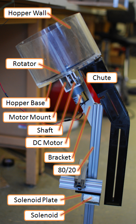
Figure 5: Chip sorter

Figure 6: Hopper mechanism
Chip Dispenser
Upon receiving a chip from the sorter, the dispenser delivers the chip to the appropriate column. The main mechanical components for this subsystem are outlined in Figure 7. A 24V, unipolar stepper motor drives the system and is connected to a precision lead screw via a flexible spring-beam coupling. In this way, rotation of the motor is converted to translation of a linear carriage. A rigid, acrylic structure is mounted to the carriage base and positions the end effector above the height of the game board. When the end effector is located above the correct column, the chip is released into the board using a solenoid, which is shown in Figure 8. To reduce frictional effects and backlash, the carriage position is zeroed at the end of each turn using a limit switch. The linear carriage is supported by two steel rods, and the lead screw is supported by ball bearings mounted in the side brackets.

Figure 7: Chip dispenser

Figure 8: End effector
Electronics
Electrical components were placed on a three-tiered wooden structure, with a benchtop power supply on the bottom, electrical circuits in the middle, and a PC power supply on top (see Figure 9). Detachable connectors for wiring between circuits and mechanical components allow the electronics structure to be transported separately. A block diagram of our electrical systems is shown in Figure 10. The benchtop power supply provides 24V to the stepper motor and 5V to the stepper motor circuit, IR sensor, and limit switch. The PC power supply provides 12V to the DC motor and two solenoids. The actual implementation is shown in Figure 11 (not visible in the figure is a prototyping board with IR sensor and limit switch circuits). The transistor switching circuit is used to actuate the solenoids on the chute and on the end effector. We built our own stepper motor driver circuit using a bi-directional shift register. The Stellaris microcontroller board was programmed using LabVIEW, and it controls all mechanical actuation. The game intelligence runs on a separate microcontroller (MBED). The MBED also controls the LEDs on the nameplate sign, which lights up blue if the machine wins and pink if it loses; the blue and pink LEDs flash alternatively to signify a tie.

Figure 9: Electronics implementation

Figure 10: Electronics power and communication

Figure 11: Electrical circuits implementation
Code
A unique feature of our machine is the use of LabVIEW software for real-time control of the motors and sensors. LabVIEW offers developers a graphical programming environment that focuses on dataflow. The block diagram for the main program, called a virtual instrument (VI), is illustrated below in Figure 12. It consists of state machines, which are case structures (lattice border) embedded in a while loop (thick border), that execute a sequence of code based on the input data that is received. For our machine, the program starts with an initialization sequence and case structures for serial communication to setup the game (green rectangles). Once the game begins, the chip sorter state machines (purple) and chip dispenser state machines (blue) execute according to our operational flowchart (from Figure 2). To make the code efficient and easier to navigate, complex functions are embedded in subVIs. Examples of subVI functions used here include DC motor control, stepper motor control, solenoid control, and serial communication.
 Figure 12: LabVIEW code (click image to enlarge)
A crucial part of our control code is the game intelligence strategy. We modified open source code (created by Keith Pomakis) that basically looks a given number of moves ahead into the game and determines which move is most advantageous for our machine. Serial communication subVIs enable the Stellaris ARM board to send an updated game state to the MBED board, which is programmed with the AI code, and receive the desired column in which to play.
A low-resolution video is embedded below. See the HD version here!
No comments:
Post a Comment